ModND Tutorial v1 by djlutz .pdf
Nombre del archivo original: ModND_Tutorial_v1_by_djlutz.pdf
Título: Microsoft Word - ModND.doc
Autor: DJ
Este documento en formato PDF 1.4 fue generado por PScript5.dll Version 5.2.2 / GPL Ghostscript 8.15, y fue enviado en caja-pdf.es el 09/04/2015 a las 17:52, desde la dirección IP 88.1.x.x.
La página de descarga de documentos ha sido vista 3699 veces.
Tamaño del archivo: 10 MB (17 páginas).
Privacidad: archivo público
Vista previa del documento
Paso a Paso para la creación del BS Mod v1
Step by Step for the BS Mod v1 creation
Intro
Intro
Este documento está basado en el original BS Mod v1 de Satandreu.
This document is based on the original one from Satandreu.
Basicamente se trata de reemplazar la pista original de la central ND y utilizar una pista de
sensor multicarril en su lugar. La razón de esto es porque el sensor multicarril ya proporciona
datos tratados que nos permite trabajar directamente a nuestro PC.
Basically, we will remove the original MCU track and attach the Multilane Sensor track to the
MCU. The reason is because the Multilane Sensor provides us processed data that allow us to
work directly with our PC.
Material
Material
Lo primero que necesitamos es una central de Ninco Digital, a ser possible uriliza una v105 o
v106 (CAR). Para saber la versión de tu consola, apretando el botón ‘Mode’, conecta el cable
de corriente a tu consola (desaconsejado usar una v104).
The first thing we need is a Ninco Digital MCU, it’s recommended to use a v105 or v106 (CAR).
In order to know your MCU version push the ‘Mode’ button and plug in the power connector (is
not recommended to use a v104 MCU).
La segunda cosa que necesitamos es un Sensor Multicarril de Ninco Digital (Ref.N40206).
The second thing we need is a Multilane Sensor from Ninco Digital (Ref. N40206)
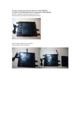
Proceso preparación Sensor Multicarril (Ref.N40206)
Process for the Multilane Sensor preparation (Ref.N40206)
Vamos a preparar la pista sensor multicarril.
We are going to prepare the Multilane Sensor
Abre la tapa posterior (6 tornillos)
Open back cover (6 screws)
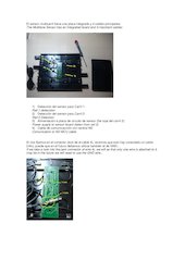
El sensor multicarril tiene una placa integrada y 4 cables principales:
The Multilane Sensor has an integrated board and 4 important cables:
1) Detección del sensor para Carril 1.
Rail 1 detecction
2) Detección del sensor para Carril 2
Rail 2 Detection
3) Alimentación a placa de circuito de sensor (Se coje del carril 2)
Power supply to sensor board (taken from rail 2)
4) Cable de comunicacción con central ND
Comunication to ND MCU cable
Si nos fijamos en el conector Jack de el cable 4), veremos que solo hay conectado un cable
(info), puede que en el futuro debamos utilizar también el de GND...
If we take a look into the jack connector of wire 4), we will se that only one wire is attached to it,
may be in the future we will need to use the GND wire...
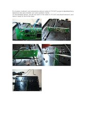
En el sensor multicarril, solo actuaremos sobre el cable 4) (TX OUT) ya que lo desoldaremos y
dejaremos listo para resoldar uno nuevo posterior mente.
On the Multilane Sensor, we will only work on the cable 4) (TX OUT) we should remove it, and
leave it ready for the former steps.
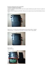
Proceso preparación de la central ND
Process to prepare the ND MCU
Vamos a preparar la central de ND: Eliminar la pista existente para poder introducir la pista de
sensor multicarril.
We are going to prepare the ND MCU: Remove the original track and add the Multilane Sensor
track.
Retira los 6 + 4 tornillos de la parte posterior de la central (pista + central)
Remove the 6 + 4 screws from the back of the MCU (track + MCU itself).
Abre la tapa
Open the cover
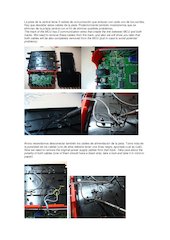
La pista de la central tiene 2 cables de comunicación que enlazan con cada uno de los carriles.
Hay que desoldar estos cables de la pista. Posteriormente también mostraremos que se
eliminan de la própia central con el fin de eliminar posibles problemas.
The track of the MCU has 2 communication wires that create the link between MCU and both
tracks. We need to remove these cables from the track, and also we will show you later that
both cables will be also completely removed from the MCU (just in case to avoid potential
problems).
Ahora necesitamos desconectar también los cables de alimentación de la pista. Toma nota de
la polaridad de los cables (uno de ellos debería tener una línea negra, apúntate cual es cuál).
Now we need to remove the original power supply cables from that track. Take care about the
polarity of both cables (one of them should have a black strip, take a look and take it in mind or
paper).
Ya tenemos la central de ND separada de su pista original.
Now we have removed the original MCU track from the ND MCU itself.
Se consuma la union de la central ND y el senor multicarril
The ND MCU and the Multilane Sensor became one.
El siguiente paso sería el soldar el cable (que comunicará con el sensor multicarril) a el Pin IN
de la central ND.
The next step should be to solder the cable (that will link with the Multilane Sensor) into the Pin
IN from the ND MCU.
Primero savaremos los 4 tornillos que fijan el circuito de la central a su alojamiento.
Firstly we need to remove the 4 screws that fix the MCU board to its housing.
Damos la vuelta a la placa.
Turn the board.
Soldaremos un cable nuevo al Pin IN.
Solder a new wire into the Pin IN
Colocamos de nuevo la placa en su alojamiento y atornillamos los 4 tornillos, pasando el nuevo
cable por la zona cercana a la situación de la pista.
We should put again the board into his housing, screwing the 4 screws, and searching a path
for the cable near to the track situation.
Preparamos la pista sensor multicarril para soldar los cables de alimentación.
We will now prepare the track for the power supply cable soldering.
Fíjate que has colocado correctamente la pista en el sentido de giro original.
Take a look into the track position in order to be sure that is the same position that it was
originally.
Soldamos los cables de alimentación manteniendo la polaridad de los mismos.
Weld the power supply cables taking care about the polarity.
CUIDADO! La zona de soldadura de la alimentación debe estar fuera de la zona muerta
de la pista!
WARNING! The soldering zone for the power supply should be outsides the dead line!
Ahora soldaremos a la placa del sensor multicarril, el cable de comunicación que soldamos con
anterioridad al Pin IN de la central de ND.
Now we will solder to the Multilane Sensor the cable that previously we soldered to the Pin IN
from the ND MCU.
Colocamos la placa del sensor de nuevo a su posición.
The Multilane board should be placed again into its original position.
En la central, desoldamos los cables de comunicación de la pista original (se podría haber
realizado al principio).
At the MCU, remove the communication wires from the original MCU track (we could have done
it on the beginning).
La pista está lista y limpia
The track is ready and clean.
Fijamos la placa del sensor por seguridad.
Fix the sensor board for safety reasons.
Cierra el conjunto teniendo en cuenta que los cables deben pasar por el hueco central para
poder cerrar bien y no hayan deformaciones.
Close the cover taking care that the wires should pass through the centre slot.
Atornilla de nuevo los 6 + 4 tornillos.
Screw again the 6 + 4 screws.
La pista ya está lista para trabajar.
The track is ready to work.
Pero antes vamos a hacer una pequeña modificación más para asegurar la correcta
alimentación del sensor multicarril (ya que éste coge la alimentación del segundo carril)
But first at all, we will add one more little modification in order to guarantee the correct power
supply to the Multilane Sensor (because the Multilane Sensor is powered up by the rail 2).
Coge 2 cables.
Take 2 wires.
Suelda el primero a un polo (GND) del raíl 1.
Weld de first wire to one pole (GND) from the first rail.
Suelda el otro extremo al mismo polo (GND) del raíl 2.
Weld the other side of that wire to the same pole (GND) from the rail 2.
Suelda el segundo cable al otro polo (V+) del raíl 1.
Weld the second wire into the other pole (V+) of the rail 1.
Suelda el otro extremo del segundo cable al otro polo (V+) del raíl 2.
Weld the other side of this second wire into the other pole (V+) of the rail 2.
Colócalos adecuadamente para evitar baches en pista.
Allocate correctly both wires in order to avoid bumps on the track.
ATENCIÓN: asegúrate de soldar correctamente en los polos iguales y hazlo en la parte
delantera de la pista (para evitar baches antes de la detección del sensor).
WARNING: be sure to weld correctly on same poles, and do that on the end side of the
track (to avoid probable bumps before the sensor detection).
Ahora ya tienes listo el BS Mod v1.
Now you have ready the BS Mod v1.
El siguiente paso sería construir el BS Interface v1 o v1.1
The next step should be to assemble the BS interface v1 or v1.1
Notas:
Notes:
A) Los pasos aquí mostrados pueden dañar los materiales originales si no se realiza
adecuadamente. El utilizar este documento o no, es de responsabilidad total tuya, no me hago
responsable de los daños ocasionados ya que este documento es de uso personal pero
compartido a quien pueda interesar.
A) The steps shown here could damage your original stuff if are not done correctly. I will not
have any responsibility on your material since this is a personal use manual, but I wanted to
share it with you.
B) Tanto el BS Mod v1 como el BS Interface v1 y v1.1, están en evolución, por lo que podrían
sufrir modificaciones en el futuro (atento a las novedades en los links sugeridos más adelante).
B) The BS Mod v1 and the BS Interface v1 and v1.1, are still in development, then they could
have modifications in the future (be aware for updates at the suggested links proposed below).
Gracias a Rick (slotforum), a Satandreu (Bourbon Slot forum), Cuñao (Bourbon Slot forum),
Guy (PcLapCounter), todos los miembros de www.slotdigital,com y el CSS por la investigación,
información, desarrollo, testeo y ayuda prestada.
Many thanks to Rick (slotforum), to Satandreu (Bourbon Slot forum), Cuñao (Bourbon Slot
forum) , Guy (PcLapCounter), all the guys from www.slotdigital.com and the CSS club for the
investigation, information, development, testing and help given.
Enlaces interesantes:
Interesting links:
Spanish:
BourbonSlot (The origin):
http://www.bourbonslot.com/phpBB3/viewtopic.php?f=16&t=549
http://www.bourbonslot.com/phpBB3/viewtopic.php?f=16&t=550
Satandreu’s BS Mod v1 Tutorial: http://www.megaupload.com/?d=478S6D55
BourbonSlot (First steps, preparing for PCLC):
http://www.bourbonslot.com/phpBB3/viewtopic.php?f=16&t=540&start=0
http://www.bourbonslot.com/phpBB3/viewtopic.php?f=16&t=597&start=0
SlotDigital.com (Working together with the members)
http://www.slotdigital.com/forums/index.php?showtopic=13236&st=0&start=0
http://www.slotdigital.com/forums/index.php?showtopic=14184
http://www.slotdigital.com/forums/index.php?showtopic=14183
http://www.slotdigital.com/forums/index.php?showtopic=13264&st=0&start=0
English:
http://www.slotforum.com/forums/index.php?showtopic=39563&st=0&start=0
Software RMS que soporta el BS Mod v1 y el BS interface v1 y v1.1
RMS software supporting the BS Mod v1 and the BS Interface v1 and v1.1:
www.pclapcounter.be
djlutz
www.slotdigital.com

Descargar el documento (PDF)
ModND_Tutorial_v1_by_djlutz.pdf (PDF, 10 MB)
Documentos relacionados


Palabras claves relacionadas
multilane
original
remove
cable
sensor
should
power
multicarril
pista
central
cables
track
board
slotdigital
alimentacion